Products
Industries
Input parameters: Three phase AC380V±10% , 50-60HZ
Reversed time: 0.5-100MS step size 100
Forward recovery time: 0.5-1000MS step size
Output mode: High speed positive and negative pulse
Cooling method: Water cooling
Power supply type: IGBT-based
Application Industry: PCB plating, such deep hole and blind hole plating process, it’s the first choice for 5G PCB board.
Positive and negative pulse power supply is mainly used in deep hole and blind hole electroplating field.
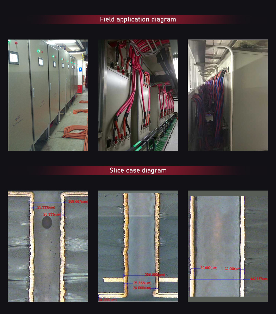
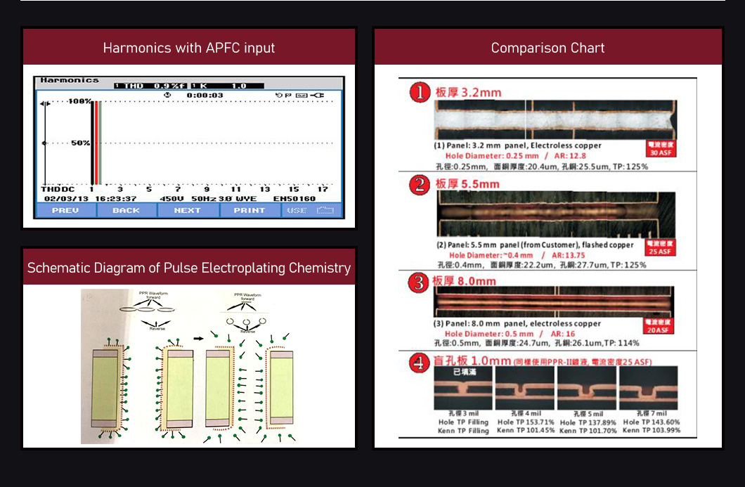
Positive and negative pulse power supply can increase electroplating speed. Improve the uniformity of copper plating, deep hole plating uniformity; Reverse pulse electroplating can control the deposition rate of copper in the high current density area, so as to improve the thickness uniformity of surface copper and pore copper, and eliminate the “dog bone” phenomenon.
The power source high-speed positive and negative pulse power supply provides positive pulse and reverse pulse in the range of 0.5-2000.0 MS. The time can be set independently. The positive pulse opening width and negative pulse opening time width can be adjusted in the full cycle respectively.
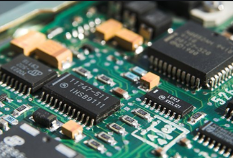
The force source high-speed positive and negative pulse power supply has a multi-stage combined waveform design mode (20 stages or more), which can output any combination of 20 or more waveforms. The positive and negative time ratio is usually 20:1, and a smaller or larger time ratio can also be used within the rated power as required, such as: 30:1, 12:1, 10:1, etc.
Synchronous control function between different pulse machines of force source high speed positive and negative pulse power supply: complete synchronization function option, the difference between machines is less than 1US.
Surface AB power supply has phase displacement (phase difference, option function) function.
Voltage, current stepless adjustable, step size 0.1ms, can find a best plating value for electroplated parts.
Power supply can be changed at any time during the working process of positive and negative time, cycle parameters, voltage, current, time, cycle all touch screen digital display and control, simple operation, intuitive and reliable instructions.
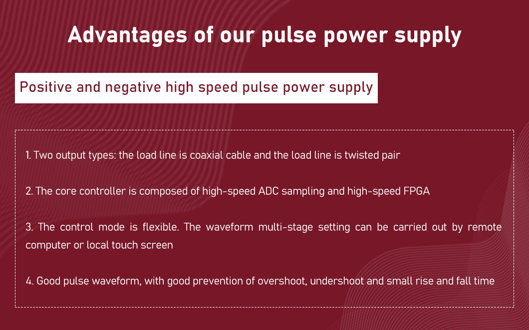
The core controller is composed of high-speed ADC sampling and high-speed FPGA. The control system has simple structure, high control precision, strong anti-interference ability and fast response speed.
High-performance single chip processor for external communication, support open Modbus protocol.
Flexible control mode, both remote computer and local touch screen can be used for waveform multi stage setting.
Good pulse waveform, with good protection against overshoot, undershoot and small rise and fall time.
CYCL0NE3 FPGA of ALTERA with frequency up to 400MHz is adopted. The FPGA is embedded with a single chip microcomputer core, which is mainly used for sub-item PID calculation and other auxiliary calculation. The logic circuit is mainly responsible for pulse formation, pulse synthesis and other functions. This also uses a special algorithm to realize the frequency conversion PWM calculation constitute a multivariate hybrid control unit.
High-speed ADC sampling feedback, to ensure that the rising edge and falling edge of the pulse can be quickly transmitted to the control core, so as to ensure good pulse waveform, with good prevention of overshoot, undershoot and small rise and fall time.
FPGA is connected to a single chip microcomputer for communication, supporting open Modbus protocol, flexible control mode.c
| Input voltage | Three phase AC380V±10% , 50-60HZ |
| Reversed time | 0.5-100MS step size 100 |
| Accuracy of current stability | ≤1% |
| Intermachine synchronization function | Yes |
| Communication mode | RS485 or other |
| Cooling method | Water cooling |
| Supporting equipment type | Gantry line and VCP line |
| Forward recovery time | 0.5-1000MS step size |
| Voltage-stabilized precision | ≤1% |
| Power factor | 0.9 |
| Waveform phase difference | Can be set |
| Communication protocol | Customized |
| Complex waveform | 20 period set |
| The output wiring | Twisted pair or coaxial cable |
| Improve depth capacity, increase electroplating efficiency by
30%-50%, optimize production capacity, improve quality, and reduce the overall cost of electroplating process. |
|
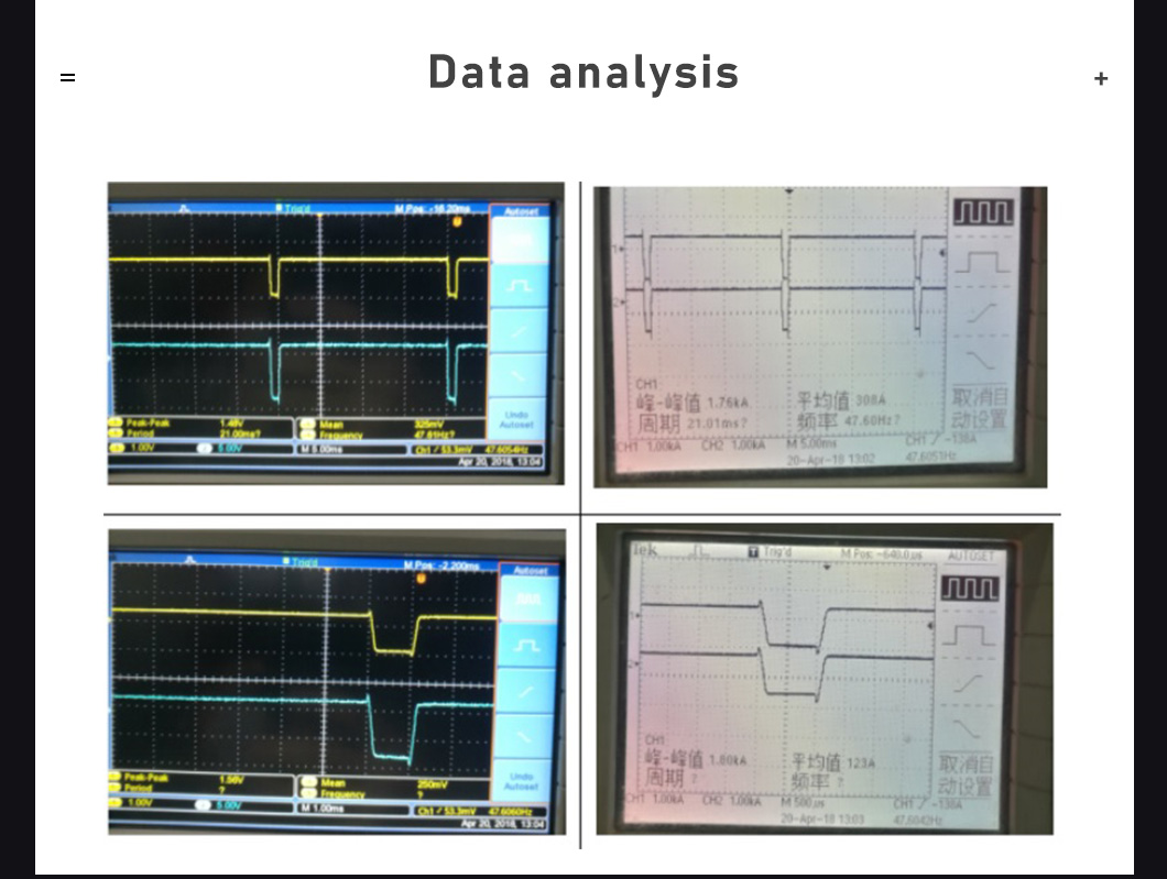
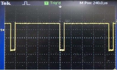
Analog waveform of normal positive and negative pulse output

Normal positive and negative pulse output actual waveform diagram
Combined pulse output analog waveform diagram

Combined pulse output actual waveform diagram

| Model | Input | Output | Dimension (H*W*L)/mm |
| HPNPS-2*Z100F300A/6V | Three phaseAC380V±10% 50HZ | .+6V/-18V +100A/-300A | 980*500*700 |
| HPNPF-2*Z150F600A/6V | Three phaseAC380V±10% 50HZ | `+6V/-18V +150A/-600A | 1900*750*800 |
| HPNPF-Z200A/6VF600A/18V | Three phaseAC380V±10% 50HZ | ·+6V/-18V +200A/-600A | 1050*580*680 |
| HPNPF-2*Z200AF600A/6V | Three phaseAC380V±10% 50HZ | ·+6V/-18V +200A/-600A | 1050*580*680 |
| HPNPF-Z250AF250A/30V | Three phaseAC380V±10% 50HZ | ·+30V/-30V +250A/-250A | 1050*580*680 |
| HPNPS-2*Z300AF900A/6V | Three phaseAC380V±10% 50HZ | `+6V/-18V +300A/-900A | 900*500*930 |
| HPNPS-2*Z400AF1200A/6V | Three phaseAC380V±10% 50HZ | ·+6V/-18V +400A/-1200A | 900*500*930 |
| HPNPS-2*Z600AF1800A/6V | Three phaseAC380V±10% 50HZ | ·+6V/-18V +600A/-1800A | 1000*600*1200 |
| HPNPF-2*Z800AF2400A/6V+P | Three phaseAC380V±10% 50HZ | `+6V/-18V +800A/-2400A | 1800*750*800 |
| HPNPS-2*Z900AF2700A/6V | Three phaseAC380V±10% 50HZ | ·+6V/-18V +900A/-2700A | 1762*750*900 |
| HPNPS-2*Z1000AF3000A/6V | Three phaseAC380V±10% 50HZ | `+6V/-18V +1000A/-3000A | 1600*700*840 |
| HPNPF-D2-Z1000A6V/F3000A/12V | Three phaseAC380V±10% 50HZ | `+6V/-12V +1000A/-3000A | 1720*750*800 |
| HPNPF-2*Z1200AF3600A/6V | Three phaseAC380V±10% 50HZ | `+6V/-18V +1200A/-3600A | 1720*750*800 |
| ※Can be customized according to requirements※ | |||
Hot Tags: Positive and Negative Pulse Power Supply,Pulse Power Supply,PCB Electroplating,PCB plating,electroplating rectifier,plating rectifier manufacturers
If you have more questions, please leave us a message and we will contact you within 24 hours.